Top search terms
Home
/
C/D Type 63A 100A 125A ATS Generator Dual Power Automatic Transfer Switch with Control Panel Circuit Breaker(125A D Type Cable)

C/D Type 63A 100A 125A ATS Generator Dual Power Automatic Transfer Switch with Control Panel Circuit Breaker(125A D Type Cable)
Circuit Breakers
Versatile Application:Designed for diverse environments, from hospitals to military facilities, ensuring continuous power.
Dual Power Interface:Equipped with RS458 Communication Interface for seamless integration with dual power systems.
High-Temperature Resilience:Operates
Versatile Application:Designed for diverse environments, from hospitals to military facilities, ensuring continuous power.
Dual Power Interface:Equipped with RS458 Communication Interface for seamless integration with dual power systems.
High-Temperature Resilience:Operates
Quantity
-
Detail
Circuit Breakers
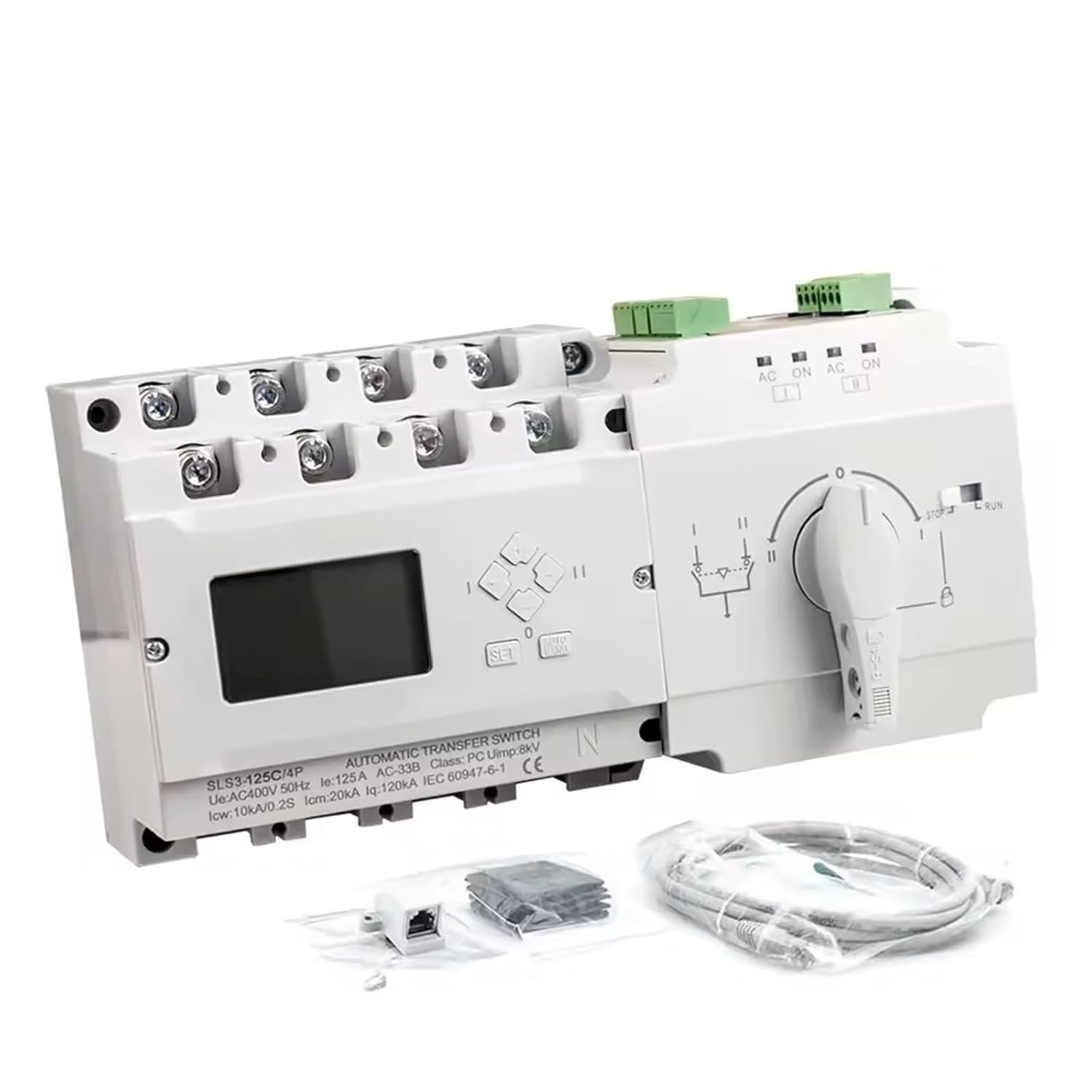
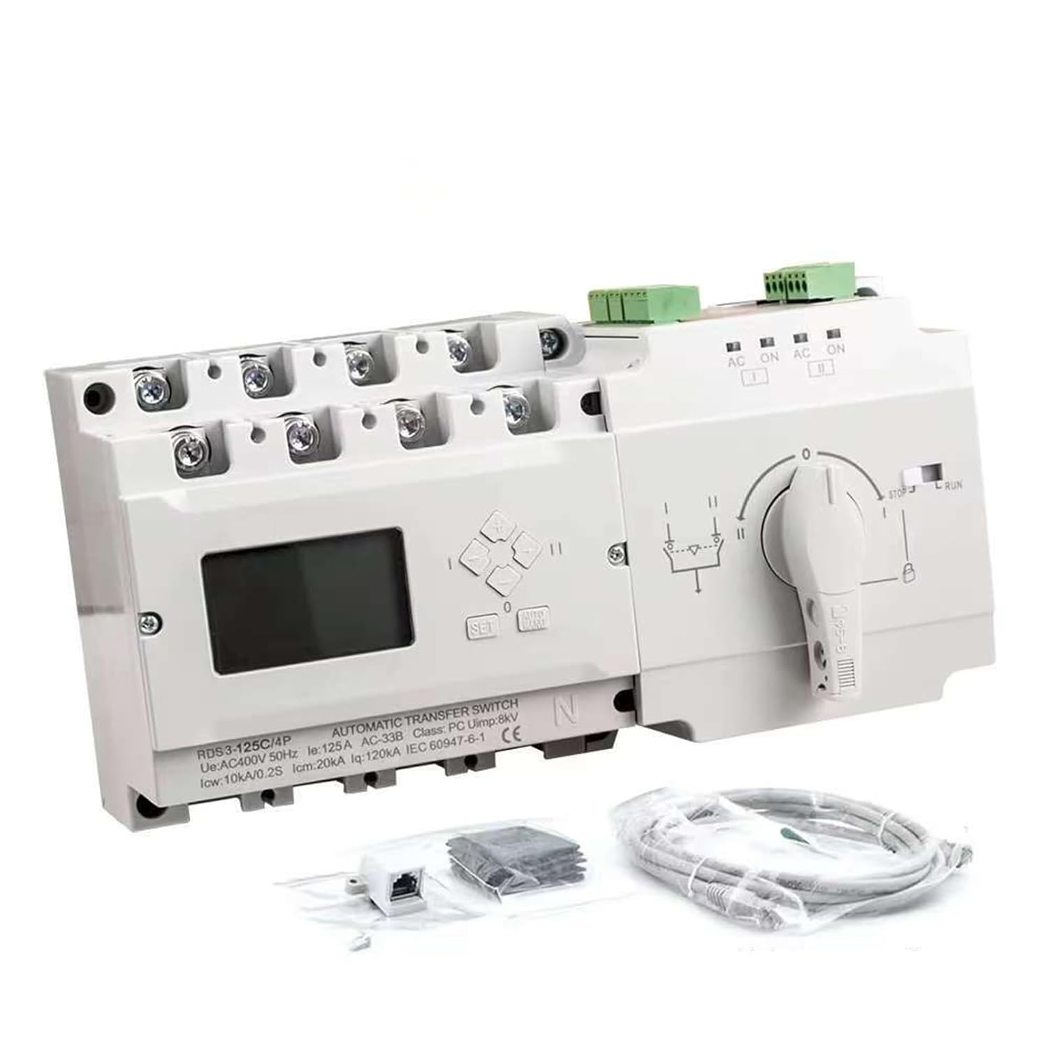
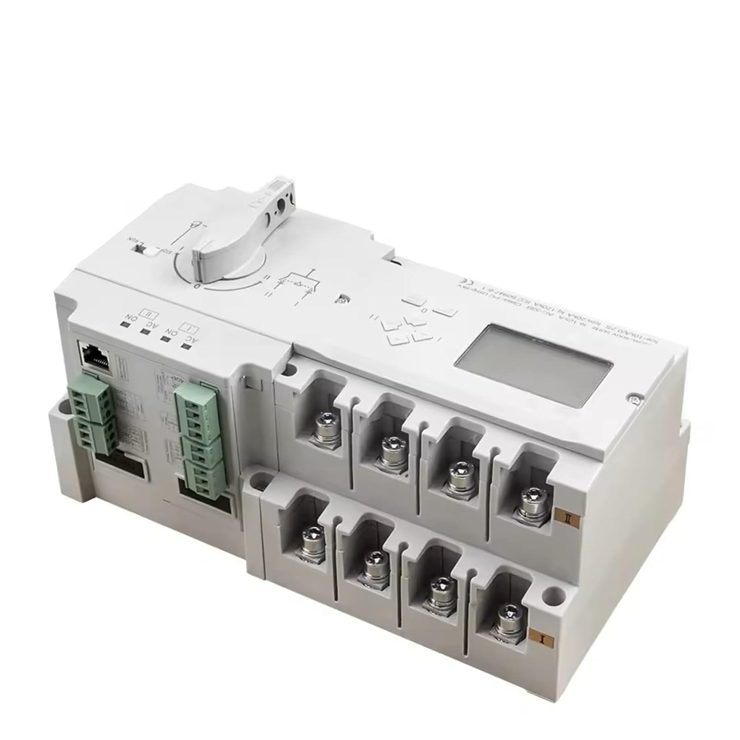
S3-125D/4PRS485 InterfaceATS Dual Power Automatic Transfer Switch Diesel Generator Parts Electric Control Curcuit BreakerS3-125C/4P
difference:
S3-125C/4P type: without RS485Communication Interface
S3-125D/4P type:withRS485Communication Interface
1. General Information
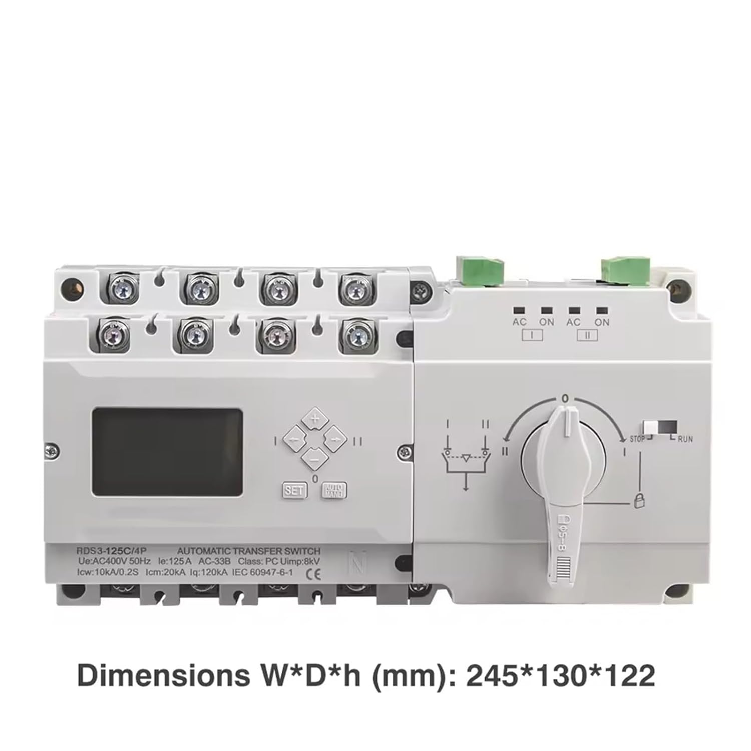
Automatic transfer switch, rated working current 16A to 630A, to be used in power systems for ensuring the continuity of the supply, by transferring a load between two power supply sources. The switch has three working positions of "Main ( I ) closing", "Standby (I) dosing" and "Double-off ()", which can be used for firfighting linkage and infequent connection and disoonnection of power supply systems. Mainly used in hospitals, shopping malls, banks, chemical industy, metallurgy, high-rise buildings, military faillieis and fre-fighting occasions where power filure is not llowed.
The product conforms to IEC60947-6-1: Lowvoltage switchgear and control gear - Part 6-1: Multiple function equipment- Transfer switching equipment
2. Working Conditions
2.1 Ambient temperature: -5'C~+40C, average temperature within 24h does not exceed +35'C.
22 Humidity: When the highest temperature is +40C, the relative humidity in the air does not exceed 50%, higher relative humidity is alwed at lower temperatures, for example, up to 90% at +25'C. Special measures should be taken for the occasional condensation due to temperature changes.
2. 3 Istallation alitude: The alitude of the istallation site does not exceed 2000m.
2.4 Pollution degree: Pollution degree is level 3.
2. 5 EMC electromagnetic comabilit: Class B (public) .
Note: If the usage environment does not meet the above conditions, it should be explained to the .
3. Transportation and Storage Conditions
3.1 The product shall not be attacked by rain or snow during transportation.
3.2 Transportation and storage temperature range: -25'C~+55'C, up to +70'C in a short time (within 24h).
8. Controller Features
8.1 Controller introduction:
Il over/undervoltage monitoring
IVII over/under frequency monitoring
II power ON running status LED indication
When the switch is working nomally, the displays the switch infomation. When inquiring/adjusting the parameters,
it displays the parameter settings; before transfer operation, transfer
Fire-fighting linkage function: The controller has a set of passive fire-fighting signal input teminals, which can accept extemal passive
fire-fighting signals, and transfer to double off position, also has a set of passive feedback signal output temminals, which can retum
the switch's in-position signal to the firefighting equipment.
Generator control function: The controller has a set of relay dry contacts to control the start and stop of the generator, and can set
the start delay and stop delay of the generator (need to be connected to the auxiliary power supply DC24V).
Communication function: Configure RS485 communication port, Modbus-RTU communication procol, which can realize remote signaling,
remote measurement, remote control, and remote adjustment (D-type contoller).
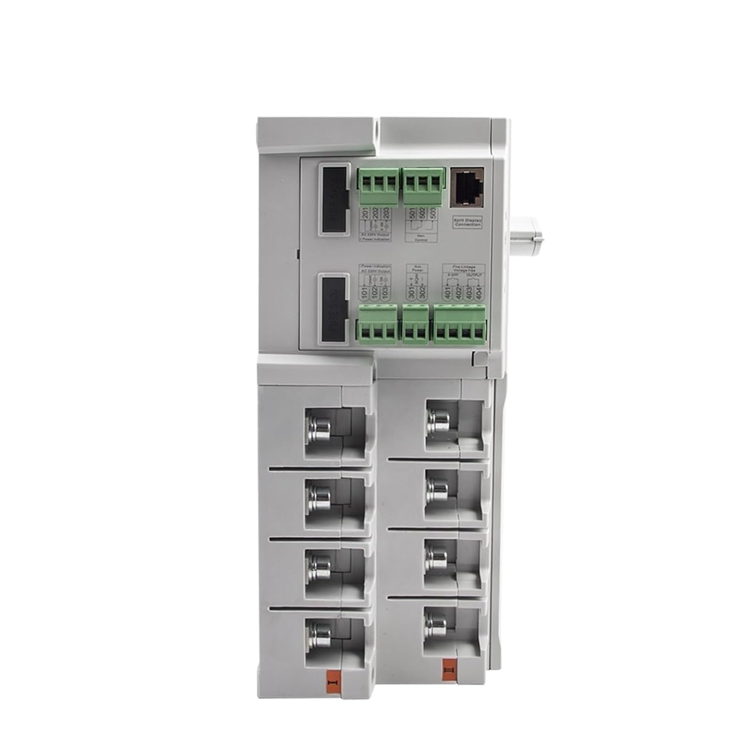
9.2 Control Terminals Instruction
<;101 ~ 103: I Power Supply Signal Output (Active Output AC230V/0.5A)
101-Source | EXTEMAL LED Indicator Common Neutral Line and 3P Neutral Line Input Terminal
101, 102-source (1) Power Signal Indication
101, 103-source (1) Closing Signal Indication
<;> 201 ~ 203: II Power Supply Signal Output (Active Output AC230V/0.5A)
201-Source II EXTEMAL LED Indicator Common Neutral Line and 3P Neutral Line Input Terminal
201, 202-source (11) Power Signal Indication
201, 203-source (11) Closing Signal Indication
Note: 101- "N1" and 201- "N2" are controlled neutral wires for 3P Products.
<;> 301 ~ 302 AUXILIARY POWER Input Port (DC12V/24V)
The Purpose of Connecting.
Generation Mode. If there is no auxilaly power support, The Start Delay Time of the Generator is 0s.
If the Generator Delay Function is Not Needed, The AUILIARY POWER SUPPL is Not Needed.
<;> 401 ~ 402 Fire Linkage Control Port (Passive)
401, 402-Frefighting Linkage Signal Input: 401, 402 Ports Can only be connected to a set of normally open passive constacts, when the
nomally. Open Contorys are dlosed, the controller immetiaately controls the switch transfer to double off public, cut off the load power.
Note: If the Fire Signal is Active, The Signal Must be transfer via a small relay
403,404-Fire linkage signal output: Inside ports 403 and 404 are a set of passive contacts that are nomally open, which are used for the feedback signal of fire- fighting actions. Ports 403 and 404 are nomally open, when the fire signal is input and the switch is switched to the double off position, the contacts 403 and 404 are closed.
Note: When the fire fighting function is activated, the switch is in the double off position. If the switch needs to resume nomal operation, press any key on the controller panel to remove the fire fighting signal)
<;>501~503 generator signal output port (passive)
When the backup ( II ) power supply is a generator group, user can realize the automatic start function after connecting to the generator contoller through teminals 501~503, inside ports of 501~503 are a group passive relay dry contact, 502 is the common teminal, 501 is the normally open point, and 502 is the normally closed point In the gnid-generator working mode and the controller is in AUTO mode,when the main power supply is nomal,
502- 501 is dlosed, and 502- -503 is disconnected, if the main power supply fils, and when the standby is out of power, 502- 503 will be closed after the generator start delay timer, and 502- 501 will be disconnected at the same time, and send signal to start the generator. After the transfer delay timer is over, the switch wil first switch to the double position. When the power generation group comes in, the oontroller will execute the gen-erator wam-up delay timer. After the delay, the switch will automatically switch to the standby power supply side. During the standby side power supply process, when the main power supply is restored, if it is nomal, the controller will control the switch to transfer to the main power supply after the retum delay timer. After the main power ON,502- 501 will be dlosed after generator stop delay timer. At the same time, 502- 503 will be disconnected and send signal to stop generator. Action flow can be referred to 8.2 Grid- generator mode.
<;>601 ~603 RS485 communication port
601--A+ 602--B- 603-- GND, communication protocol MODBUS-RTU.
==========
Hign-concerned Chemical : None
Model Number : RDS3-125C/4P,RDS3-125D/4P
Certification : TUV/CE certificate
current : 125A
pole : 4P
S3-125C/4P : without RS458 Communication Interface
S3-125D/4P : with RS458 Communication Interface
voltage : AC400v
frequency : 50HZ -
Customer ReviewsNo comments